Entities
Entities are the graphical objects in dxf.
INFO
- All entities described here are added directly to the model space block(
*Model_Space).
All Entities have some common options:
trueColor,colorNumber,layerName,visible,lineTypeandlineTypeScale.
ARC
An arc is a portion of the circumference of a circle. (See more in Wikipedia)
import { DxfWriter, point3d } from "@tarikjabiri/dxf";
const dxf = new DxfWriter();
dxf.addArc(point3d(0, 0), 10, 0, 45);
// or
const myArc = dxf.addArc(point3d(0, 0), 10, 0, 45); // If you want a reference to the added arc.
ATTRIB
The ATTRIB (DXF Reference) entity represents a text value associated with a tag. In most cases an ATTRIB is appended to an Insert entity, but it can also be used as a standalone entity.
Attrib should go right after Insert:
import { DxfWriter, point3d } from "@tarikjabiri/dxf";
const dxf = new DxfWriter();
const doc = dxf.document;
const blockA = doc.addBlock('blockNameA');
const blockB = doc.addBlock('blockNameB');
const msp = doc.modelSpace;
{
  const insertA = msp.addInsert(blockA.name, point3d(0, 0))
  const attribA = msp.addAttrib(point3d(0,0), 100, 'attributeName', 'attributeValue', insertA)
}
{
  const insertB = msp.addInsert(blockB.name, point3d(0, 0))
  const attribB = msp.addAttrib(point3d(0,0), 100, 'attributeName', 'attributeValue', insertB)
}
CIRCLE
A circle is a shape consisting of all points in a plane that are at a given distance from a given point, the centre. Equivalently, it is the curve traced out by a point that moves in a plane so that its distance from a given point is constant. The distance between any point of the circle and the centre is called the radius. (From Wikipedia)
import { DxfWriter, point3d } from "@tarikjabiri/dxf";
const dxf = new DxfWriter();
dxf.addCircle(point3d(0, 0), 10);
// or
const myCircle = dxf.addCircle(point3d(0, 0), 10); // If you want a reference to the added circle.
ELLIPSE
An ellipse is a plane curve surrounding two focal points, such that for all points on the curve, the sum of the two distances to the focal points is a constant. As such, it generalizes a circle, which is the special type of ellipse in which the two focal points are the same. (From Wikipedia)
import { DxfWriter, point3d } from "@tarikjabiri/dxf";
const dxf = new DxfWriter();
dxf.addEllipse(point3d(100, 100), point3d(50, 0), 0.5, 0, 2 * Math.PI);
// or
const myEllipse = dxf.addEllipse(
  point3d(100, 100),
  point3d(50, 0),
  0.5,
  0,
  2 * Math.PI
); // If you want a reference to the added ellipse.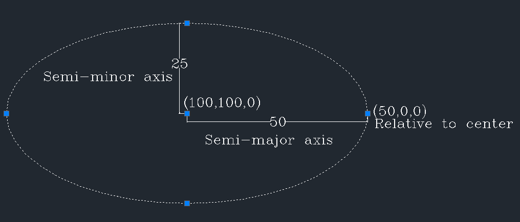
3DFACE
A 3d face is flat surface with 4 corners.
import { DxfWriter, point3d } from "@tarikjabiri/dxf";
const dxf = new DxfWriter();
dxf.add3dFace(
  point3d(0, 0),
  point3d(0, 100),
  point3d(100, 100),
  point3d(100, 0)
);
// or
const my3dFace = dxf.add3dFace(
  point3d(0, 0),
  point3d(0, 100),
  point3d(100, 100),
  point3d(100, 0)
); // If you want a reference to the added 3dface.
You can controle the visibilty of the edges of the 3d Face by using the convenience methods:
my3dFace.setFirstEdgeVisible(true);
my3dFace.setSecondEdgeVisible(true);
my3dFace.setThirdEdgeVisible(true);
my3dFace.setFourthEdgeVisible(true);

//Or all of them at once
my3dFace.setEdgesVisible(true);
By default all of the edges are visible.
Also you can set the visibilty in the options:
import { DxfWriter,
  point3d,
  InvisibleEdgeFlags,
} from "@tarikjabiri/dxf";
const dxf = new DxfWriter();
dxf.add3dFace(
  point3d(0, 00),
  point3d(0, 1000),
  point3d(100, 1000),
  point3d(100, 00),
  {
    invisibleEdges: InvisibleEdgeFlags.First | InvisibleEdgeFlags.Fourth,
  }
);
// This will make the first and fourth edges invisible.
TIP
- To define a 3d face with only 3 corners, make the fourth same as the third corner 😉.
HATCH
The HATCH entity fills an enclosed area defined by one or more boundary paths with a hatch pattern : solid or gradient.
To create a hatch you need to define :
- A boundary path or multiple.
- Polyline path is the simple way
- Edges path is the flexible way
- A hatch pattern solid or gradient.
Define a polyline path :
import { HatchPolylineBoundary, vertex } from "@tarikjabiri/dxf";
const polyline = new HatchPolylineBoundary();
polyline.add(vertex(0, 0));
polyline.add(vertex(0, 10000));
polyline.add(vertex(10000, 10000));
polyline.add(vertex(10000, 0));
// You can define a bulge for the vertex also
polyline.add(vertex(10000, 0, 10));
Define a edges path :
import { HatchEdgesTypeData, point2d } from "@tarikjabiri/dxf";
const edges = new HatchEdgesTypeData();
edges.addLineEdgeData(point2d(0, 0), point2d(0, 10000));
edges.addLineEdgeData(point2d(0, 10000), point2d(10000, 10000));
edges.addLineEdgeData(point2d(10000, 10000), point2d(10000, 0));
edges.addLineEdgeData(point2d(10000, 0), point2d(0, 0));
// For now LineEdge and ArcEdge are supported
Create a HatchBoundaryPaths instance :
import { HatchBoundaryPaths } from "@tarikjabiri/dxf";
const boundary = new HatchBoundaryPaths();
// Add the defined path
boundary.addPolylineBoundary(polyline); // You can add multiple
// Or
boundary.addEdgesTypeData(edges); // You can add multiple
WARNING
- You can define one type of paths
HatchPolylineBoundaryorHatchEdgesTypeData, not both at same time.
Next you define the fill pattern solid or gradient :
import { pattern, gradient, GradientType } from "@tarikjabiri/dxf";
// Pattern
const mypattern = pattern({
  name: HatchPredefinedPatterns.STEEL,
  // Other properties you can define optionally
  // angle?: number;
  // scale?: number;
  // double?: boolean;
});
// Gradient
const mygradient = gradient({
  firstColor: 5,
  type: GradientType.CYLINDER,
  // Other properties you can define optionally
  // secondColor?: number;
  // angle?: number;
  // definition?: number;
  // tint?: number;
});
// Solid
const solid = pattern({
  name: HatchPredefinedPatterns.SOLID
});
Now you have a boundary path and a fill pattern, you can add the hatch :
import { DxfWriter } from "@tarikjabiri/dxf";
const dxf = new DxfWriter();
const hatch = dxf.addHatch(boundary, mypattern);
// Or
const hatch = dxf.addHatch(boundary, mygradient);
// Or
const hatch = dxf.addHatch(boundary, solid);
TIP
You change the color of the pattern like this:
import { DxfWriter } from "@tarikjabiri/dxf";
const dxf = new DxfWriter();
const hatch = dxf.addHatch(boundary, mypattern);
// Or
const hatch = dxf.addHatch(boundary, solid);
hatch.colorNumber = 3;
// Or change the color of the layer, or the layer itself
hatch.layerName = someLayer.name; // With the wanted color.
// Or by passing the options
const hatch = dxf.addHatch(boundary, solid, {
	colorNumber: 3,
	layerName: someLayer.name,
});
WARNING
- This way you can add only non-associative hatches.
IMAGE
import { DxfWriter, point3d } from "@tarikjabiri/dxf";
const dxf = new DxfWriter();
dxf.addImage(
  ".\\image-name.png", // Or the absolute path of the image if it isn't int the same folder.
  "image-name",
  point3d(462419.04, 576568.45), // Insertion point of the bottomLeft corner of the image.
  1792, // the width of the image
  1280, // the height of the image
  1, // Scale
  0 // rotation
);
// or
const myimage = dxf.addImage(
	'.\\image-name.png', // Or the absolute path of the image if it isn't int the same folder.
	'image-name',
	point3d(462419.04, 576568.45), // Insertion point of the bottomLeft corner of the image.
	1792, // the width of the image
	1280, // the height of the image
	1, // Scale
	0 // rotation
); // If you want a reference to the added image.
INSERT
It's convenient to create reusable blocks at once and use them all over the places you want. After defining your blocks, you can insert them with the INSERT entity. See example code below:
import { DxfWriter, point3d } from "@tarikjabiri/dxf";
const dxf = new DxfWriter();
// Define your block
const myBlock = addBlock("block1");
myBlock.addCircle(point3d(0, 0), 50);
myBlock.addRectangle(point2d(-35.3553, 35.3553), point2d(35.3553, -35.3553));
// Insert it when and where ever you want.
dxf.addInsert(myBlock.name, point3d(0, 0));
// or
const myInsert = dxf.addInsert(myBlock.name, point3d(0, 0)); // If you want a reference to the added insert.
LINE
import { DxfWriter, point3d } from "@tarikjabiri/dxf";
const dxf = new DxfWriter();
dxf.addLine(point3d(0, 0), point3d(100, 100));
// or
const line = dxf.addLine(point3d(0, 0), point3d(100, 100)); // If you want a reference to the added line.
LWPOLYLINE
import { DxfWriter, point3d } from "@tarikjabiri/dxf";
const dxf = new DxfWriter();
const vertices = [
  {
    point: point2d(0, 0),
  },
  {
    point: point2d(100, 100),
  },
  {
    point: point2d(100, 200),
  },
  {
    point: point2d(0, 300),
  },
];
dxf.addLWPolyline(vertices, {
  flags: LWPolylineFlags.Closed,
});
// or
const lwpolyline = dxf.addLWPolyline(vertices); // If you want a reference to the added lwpolyline.
POINT
import { DxfWriter, point3d } from "@tarikjabiri/dxf";
const dxf = new DxfWriter();
dxf.addLine(point3d(0, 0), point3d(100, 100));
// or
const line = dxf.addLine(point3d(0, 0), point3d(100, 100)); // If you want a reference to the added point.
POLYLINE
SPLINE
import { DxfWriter, point3d } from "@tarikjabiri/dxf"
const dxf = new DxfWriter()
const mySpline = dxf.addSpline({
  controlPoints: [
    point3d(0, 0),
    point3d(10, 10),
    point3d(20, 10),
    point3d(30, 20)
  ],
  // You can set these parameters optionally:
  // fitPoints: [],
  // degreeCurve: 3,
  // flags: SplineFlags.Periodic,
  // knots: [],
  // weights: []
})
TEXT
import { DxfWriter, point3d, TextHorizontalAlignment, TextVerticalAlignment } from "@tarikjabiri/dxf";
const dxf = new DxfWriter();
dxf.addText(point3d(20, 20), 1, 'GGWP', {
	rotation: 30,
	horizontalAlignment: TextHorizontalAlignment.Center,
	verticalAlignment: TextVerticalAlignment.Middle,
	secondAlignmentPoint: point3d(20, 20),
});
// or
const text = dxf.addText(point3d(20, 20), 1, 'GGWP', {
	rotation: 30,
	horizontalAlignment: TextHorizontalAlignment.Center,
	verticalAlignment: TextVerticalAlignment.Middle,
	secondAlignmentPoint: point3d(20, 20),
}); // If you want a reference to the added text.